Temperature measurement by Resistance Temperature Detector
Published on Feb28, 2023 | Category: basicRTD, Resistance Temperature Detector. In Industries Resistance Temperature Detector Used As Temperature Sensor. In Resistance Temperature Detector Resistance Change When Temperature Change. Resistance Of Rtd Wire Increases When Temperature Of Wire Increases. Commonly Resistance Temperature Detector Made Of Platinum, Copper, Nickel But Most Widely Used Material Is Platinum. In Resistance Temperature Detector Material Is Positive Temperature Coefficient Means When Material Temperature Increases Than Resistance Also Incenses. Output Of Resistance Temperature Detector Is Resistance.The PT100 is a common RTD constructed from platinum with a resistance of 100 Ω at 0°C. RTD elements are also available with 0°C resistances of 200, 500, 1000, and 2000 Ω .
basic principle of Resistance Temperature Detector
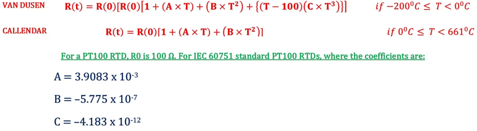
basic principle of Resistance Temperature Detector of an RTD is based on the Callendar-Van Dusen equation. According to equation the relationship between temperature and electrical resistance changes proportionally. The Callendar-Van Dusen equation is a mathematical equation that relates the resistance of a resistance temperature detector (RTD) to its temperature. It is used to convert the measured resistance of an RTD into an accurate temperature reading. Callendar-Van Dusen equation, where first equation given by Van Dusen and second equation is simplified by Callendar as follow:
note: above is simplified version as standard of DIN EN IEC 60751
-
where:
- R(T): resistance at T°C
- R(0) = resistance at 0°C
RTD ELEMENTS
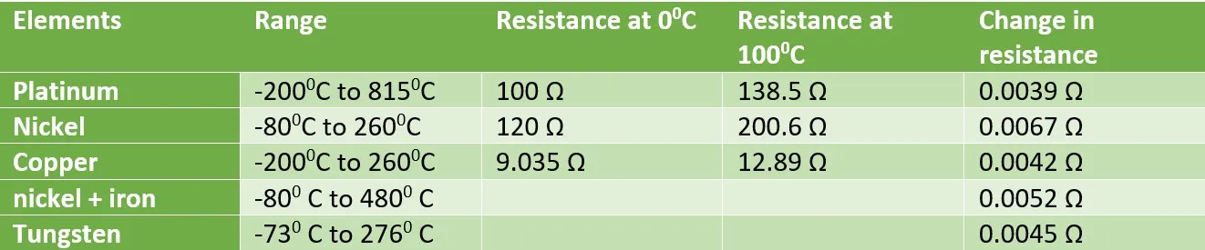
RTD elements are the actual sensing components that detect changes in temperature. They are typically made from platinum, although other metals such as nickel or copper can also be used. Following material are used for constructing of RTD
- Platinum: high accuracy, stability, and wide temperature range.
- nickel: use in a narrow temperature range.
- copper: least expensive
- nickel + iron(Balco) Balco RTD are made of a special alloy of nickel, chromium, and aluminum. Used in HVAC applications due to their high sensitivity to temperature changes.
- Tungsten: high sensitivity, accuracy
- carbon resistors: are used in ultra-low temperatures (−273 °C to −173 °C).
types of rtd
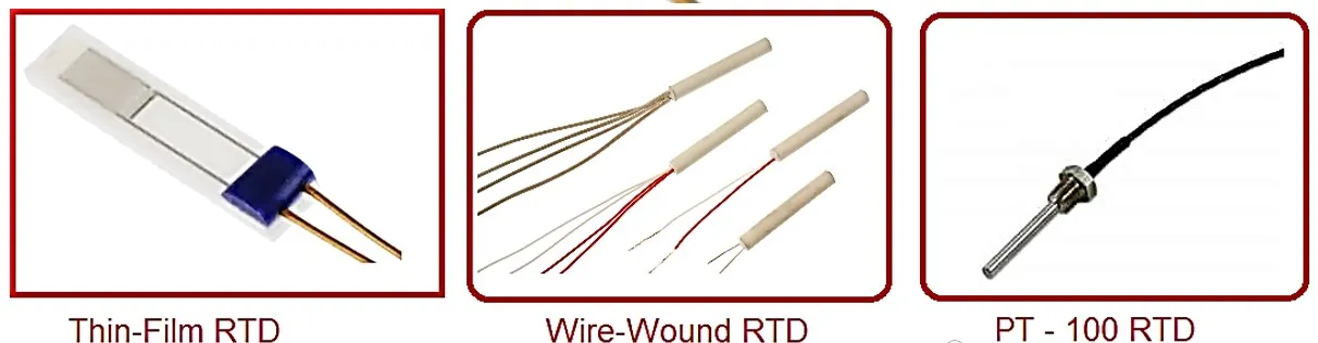
in industry used thin-film, wire-wound, and coiled elements. For ultra-low low temperature carbon resistor are used. But most widely used Wire-wound RTD & Thin-film RTD elements
- thin-film RTD on a ceramic substrate sensing element formed by depositing a very thin layer of resistive element such as platinum, nickel etc. They have a limited temperature range.
- wire-wound RTD sensing wire(nickel, platinum, copper etc.) wrapped around an insulating core. core is round or flat and electrical insulator. have minimize strain and consequential drift.it have greater accuracy, for wide temperature ranges.
- Coiled elements: small coil of sensing element(nickel, platinum, copper etc.) placed in ceramic or glass housing filled with a non-conductive powder. have largely replaced wire-wound elements because have strain free, contract free from other materials.
- PT100 RTD Sensors pt= platinum and 100 means 100 ohms at at 0 °C resistance factor.
- PT1000 RTD Sensors pt= platinum and 1000 means 1000 ohms at at 0 °C resistance factor.
- Ni120 RTD Sensors NI= nickel and 120 ohms at at 0 °C resistance factor.
- Cu100 RTD Sensors cu= copper and 100 ohms at at 0 °C resistance factor.
Wiring configurations and electrical circuits
RTD Sensors are different type of wire configurations these wire configuration increases accuracy of RTD. The most common configuration is three wire and four wire configuration.RTDs are made in three different wiring configurations. Each wiring configuration requires a different excitation and circuit topology to reduce the measurement error Below shown different type of RTD configuration. Resistance of RTD measured by Unbalanced Wheatstone bridges. Variation of resistance make variation in voltage as shown
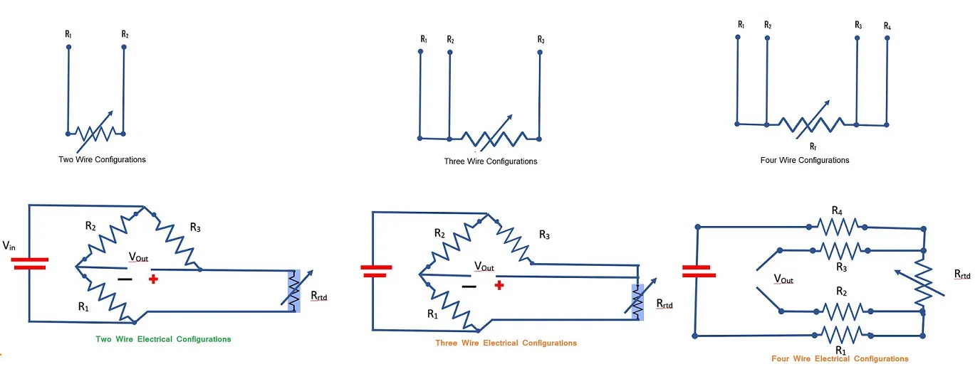
- two wire configurations simplest, low accuracy
- three wire configuration most widely used, high accuracy
- four wire configuration accuracy is greater than three wire configuration.
How to connect rtd to the plc?
you can connect rtd to plc directly if you have RTD input module or if you also connect analog card first you have to connect the RTD to a transmitter to convert signal generated from RTD to the standard signal of the AI module, then connect the transmitter output to the AI card. see some below image for connection we discuss on seprate article.
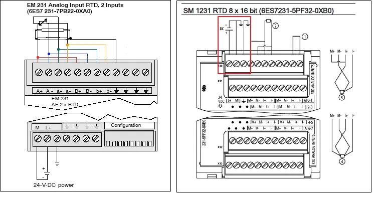
After applying power to the RTD module, the module performs internal calibration for the Analog to Digital converter. During this time the module reports a value of 32767 on each channel until valid data is available on that channel. The PLC program may need to allow for this initialization time.
use of RTD in industry
RTD uses for temperature measurement in industry. for example motor temperature, winding temperature, panel temperature, bag house temperature, coal mill temperature etc.